Technical Newsletter vol. 33 : Problem solutions in MIM process; debinding and sintering process
Problem solutions in MIM process; debinding and sintering process
As the last issue in 2021, we would like to introduce some common defects and the problem solutions in the debinding and sintering process in metal injection moulding (MIM).
The common defects in the MIM debinding process
The binder in powder metallurgy is elemental material for giving metal powder the flowability in the mould. Especially in MIM, the design tends to be more complicated than compaction metallurgy, thus 10 times or larger volumes of binder in compaction metallurgy are mixed in MIM feedstock (material). However, none of the binder related compositions can be retained in the final component, thus the binder should be decomposed completely in the debinding and sintering process. The majority of the binder should be decomposed in the debinding process yet a very little amount of binder will be decomposed in the sintering process. It is because the binder also works as a support of the component shape until the sintering starts.
In the debinding and sintering process, some appearance defects, such as; cracking, slumping, warpage, blisters and mechanical property loss by chemical composition changes are commonly seen.
Problem solution in moulding parameter
The airflow design in the mould is also important for stable injection moulding. The injection moulding process is normally held at atmospheric pressure. Thus, when the feedstock arrives at the cavity, there is some air remaining. The remaining air should be pushed out from the cavity without increasing feedstock pressure when the mould is completely closed. Unfortunately, the airflow and the flash creation is a trade-off relationship. The injection parameter optimisation is also useful for stable serial production. The ideal small gate size with minimal clearance mould is expected injection difficulties, however, lower injection speed can minimise the share stress change, good airflow without creating flash. On the other hand, low injection speed lead weld lines or flow marks due to the low viscosity of the feedstock. When the injection speed is low, the time of flowing the feedstock in the cavity becomes long and the feedstock temperature is dropped. The low temperature feedstock has a high viscosity and the weld line or flow mark, which is not only leading to the appearance issue but also mechanical property problem, will be observed
Problem solutions in the debinding and sintering
In the debinding process, thermal, organic solvent and catalytic reactions are applied for decomposing the binder. The thermal decomposition is the easiest method, however it is a time consuming method. The laminar flow in the furnace improves the efficiency since the decomposed binder is in gaseous phase. The binder will be decomposed sequentially at the certain temperature range, thus the blistering is commonly observed if the temperature increase rate is too high.
With the solvent debinding, the green body is submerged into liquid or vaporous solvent to decompose the binder. Cracking, slumping or blistering is commonly observed due to the binder swelling and/or residual stress difference between the surface and interior. It is possible to avoid these problems by selecting appropriate organic solvents and temperature control.
The catalytic debinding uses sublimation of binder, thus it is possible to decompose the binder in relatively short processing time with minimising the deformation. However, with a strong acidic atmosphere, the applicable metal material option is limited.
In the sintering process, the necking, which is bridging the metal powders by thermal diffusion, starts at the sintering temperature. Once the necking starts, the shrinking is observed and increases the density, thus before starting the necking reaction, all the organic components should be decomposed and gas between the powders should be removed. In the sintering process, the unwanted chemical reaction, such as oxidation or carbonisation, leads to mechanical property loss, therefore a precise atmosphere control with low heating rate at the beginning of the process is required. Also, when it reaches the sintering temperature, some additive metal can be evaporated. Thus, again the atmospheric control is important to minimise the additive metal loss to maintain the alloy property. To avoid the additive metal loss, the sintering in the inert gas atmosphere is applied in some cases.
μ-MIM®︎ debinding and sintering technology
In our μ-MIM®︎ process, we mainly use thermal debinding with 2 in 1 furnace, that the debinding and sintering process can be done in a furnace. It is required accurate and precise atmospheric control to realise high quality sintered components, thus we have cooperated with the furnace manufacturer to develop the 2 in 1 furnace. This furnace is crucial to realise stable serial production of small complicated designed MIM parts. Additionally, our debinding and sintering technology is applied in the additive manufacturing field.
Please leave your debinding and sintering problems to us.
Reference; Handbook of Metal Injection Molding Second edition (ISBN: 978-0-08-102152-1)
COLUMN

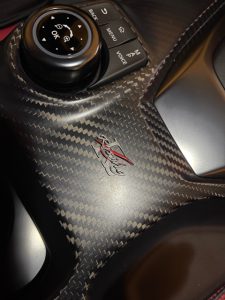
*Photo of the logo made by our 3D printer
Hello. I am Sumiyo Morita, responsible for the administration and accountant. I have been working here longer than any other staff, except our company president. Since I have significant experience in the company, I ensure that the combined efforts of the team result in a smooth outcome. My background is not technical but over time I learnt about the technical aspects of my work, the customers’ needs and expectations. I am a theater-going person so reopening the theaters makes me happy even though it is still limited. Nowadays I am also interested in automotive racing. Fortunately, I got to know a professional driver and got a chance to support his team by supplying his logo mark printed by our 3D printer.
